
Orbit 60 PPM (142M8515): What the Module Does and What the 90% Load Warning Means
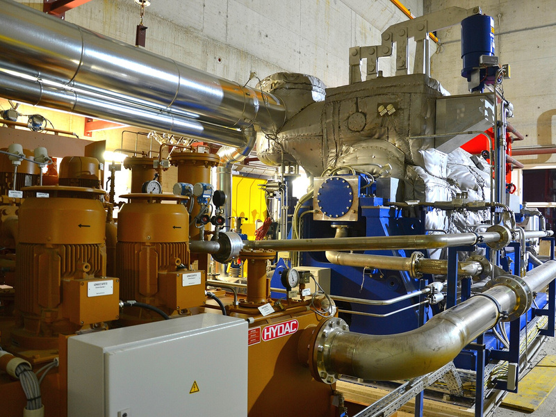
TL;DR: The Bently Nevada Orbit 60 Protection Processing Module (PPM) is the centralized compute engine of the protection system: it extracts every protection measurement and performs the alarm determinations for the input modules in the chassis. 142M8515 is the number of the PPM datasheet (Rev. A), not a module order code — the ordering number is 60R/PPM01. Baker Hughes documents a System Utilization Calculator in Orbit Studio that shows a warning when a PPM reaches 90% processing capacity and recommends adding one PPM, or two if the system is redundant. That 90% figure is a capacity-planning warning, not a trip setpoint.
Spare-parts catalogues blur the line between a Bently Nevada document number and a hardware number. The PPM is a good example: the module is widely advertised as “142M8515”, because that is the number printed on the datasheet that describes it. Anyone who quotes 142M8515 as an order code is quoting a PDF. This guide checks the module against the Orbit 60 Protection Processor Module datasheet (142M8515 Rev. A), the Orbit 60 System Overview datasheet (137M5182 Rev. K) and Baker Hughes’ own Orbit 60 articles, and separates what the PPM does from what the surrounding modules do.
Is 142M8515 the PPM part number or a datasheet number?
142M8515 is the document number of the Orbit 60 Protection Processor Module datasheet, Rev. A. It is not the module order code. Resellers list the PPM as 60R/PPM01 and link that same 142M8515 PDF as its specification sheet, while the system overview carries its own number, 137M5182. Quote 60R/PPM01 when you need the module.
The two numbering systems are easy to tell apart once you know what to look for. Bently Nevada datasheets carry a six-digit, letter, four-digit document number in the page header — 142M8515 Rev. A for the PPM, 137M5182 Rev. K for the system overview, 137M0698 for the dynamic input modules. Hardware carries a 60R/ prefix and a short functional code, such as 60R/PPM01 for the PPM or 60R/CHA for the chassis.
This matters at the quotation stage. A purchase order raised against 142M8515 describes a document, not a module, so the supplier has to interpret what you actually want — and may ship the wrong slot card or quote a kit instead. The same discipline applies to any automation purchase; our guide to verifying an automation part number before you order sets out the checks we use.
What does the Orbit 60 PPM actually compute?
The PPM is the computational engine of the Orbit 60 monitoring system. It extracts all machinery measurements for the protection system, performs alarm determinations, and publishes measurements and statuses to the other modules for collection and external communication. Signal digitisation happens in the separate four-channel dynamic input modules, not in the PPM.
In the datasheet’s wording, the PPM “analyzes signals from transducers, generates measurements and statuses and publishes them to other modules.” That description defines both sides of its job: it is where protection values are calculated and where alarm decisions are made, and it is a publisher rather than a store.
The processing itself covers the measurement types the system is configured for — 1X, 2X and nX amplitude and phase, bandpass and direct values, bias, thrust and differential expansion, case expansion, eccentricity, shaft absolute, speed, reverse rotation, valve position and process variables. Alarm handling is configured in the same module: four setpoint levels per measurement, alarm time delays of 100 ms to 60 s for vibration and position measurements and 1 s to 60 s for speed, and up to 32 protection states driven by discrete contacts or configurable measurement ranges.
What the PPM does not do is equally important. It does not store trend data for System 1 — that is the Condition Monitoring Module. It does not speak Modbus, EGD or OPC to a DCS — that is the Communications Gateway. And it does not digitise field signals — that is the input module in front of it.
Which Orbit 60 module does which job?
Orbit 60 splits protection, monitoring and communications across separate modules: the SIM defines the system, PPMs compute protection values and alarms, CMMs buffer condition-monitoring data for System 1, CGWs carry process data to DCS and PLCs, and PIMs supply redundant power. Input, relay and recorder modules handle field signals and outputs.
| Module | Function in the system | What it does not do |
|---|---|---|
| System Interface Module (SIM) | Defines the system, holds configuration, provides system contacts and the protection fault relay, and exposes three Ethernet ports | Does not compute protection values |
| Protection Processing Module (PPM) | Extracts protection measurements, performs alarm determinations, publishes values and statuses | Does not digitise inputs or store trends |
| Condition Monitoring Module (CMM) | Listens to all system data and buffers it for System 1 over the business network; occupies two slots | Cannot write to the protection system |
| Communication Gateway (CGW) | Exchanges measurements, alarms, statuses and process data with external hosts over Modbus and EGD | Does not participate in the protection decision |
| Power Input Module (PIM) | Connects +21 Vdc to +32 Vdc input power; two PIMs fit the first slot for redundancy | Does not condition signals |
| Bridge module (BRG) | Links chassis into one system in linear or star topologies | Does not process measurements |
| Input modules (PAV, PAA, KPH, RTD, PVD and others) | Digitise dynamic or static field signals in four- or six-channel groups | Do not make protection decisions |
| Relay and recorder output modules | Provide trip contacts and proportional 4-20 mA, 1-5 Vdc or 0-10 Vdc outputs | Do not compute setpoints |
One correction is worth stating plainly, because it circulates in comparison articles: there is no “Asset Processing Module” or APM in the Orbit 60 module list. The condition-monitoring counterpart to the PPM is the CMM. If a document describes an APM in an Orbit 60 chassis, that document is not using Bently Nevada’s module names.
How many sensors can one PPM support?
Baker Hughes states that one PPM typically supports 80 dynamic and hundreds of static points, with capacity depending on how much processing each input requires. Systems that need more processing add PPMs, and protection systems are recommended to run redundant PPMs. The SIM itself defines a system of up to 88 dynamic channels.
The “80 dynamic points” figure is a typical number, not a hard channel limit, because the load depends on measurement complexity. A channel configured for direct amplitude only costs less processing than one carrying 1X, 2X and nX vectors, bandpass filtering and multiple averaged spectra. That is why the same module can serve a small machine train with headroom to spare and run short on a dense, heavily processed application.
Two system-level limits frame the calculation. A single SIM defines a system of up to 88 dynamic channels and up to four chassis linked by Bridge modules; the initial release supported 48 dynamic channels in one chassis. Above the processing capacity of one PPM, additional PPMs are added to the same system rather than splitting the machine train across systems.
What does the 90% PPM utilisation warning mean?
Orbit Studio includes a System Utilization Calculator that evaluates the remaining capacity of the PPMs in a system. Baker Hughes states that when a PPM reaches 90% processing capacity, Orbit Studio displays a warning and recommends adding another PPM, or two PPMs if the system is redundant. The threshold is a planning warning, not a trip or interlock.
The datasheet wording is unambiguous, and it is worth quoting rather than paraphrasing:
“The Orbit Studio Configuration Software provides a System Utilization Calculator to evaluate the remaining capacity of the PPMs in your system. If a PPM processing capacity reaches 90%, a warning indicator is displayed in Orbit Studio software, and it is recommended to add another PPM or 2 PPMs if the system is redundant.” — Orbit 60 Protection Processor Module datasheet, 142M8515 Rev. A
Three things follow from that sentence. First, the calculator lives in Orbit Studio, the configuration software, so the 90% figure is an engineering and configuration indicator — it is not published as a DCS alarm, a relay output or a protection setpoint. Second, 90% is a recommendation threshold, not a capacity ceiling: the datasheet does not state that the PPM stops processing at 90%, and it does not describe a hard limit. Third, the corrective action scales with the architecture — one PPM in a simplex system, two in a redundant system, because a redundant pair is sized as a pair.
The practical reading for a project engineer is headroom. A PPM sitting at 89% today has almost no room for the points that always get added after commissioning: a spare channel per bearing, an extra Keyphasor, a process variable brought in through the gateway. Keeping the calculated load comfortably below the warning line avoids a mid-project slot and module purchase, which is exactly the kind of late change that drives retrofit cost. If you are planning the wider condition-monitoring layer at the same time, the bidirectional data path is covered in our guide to Orbit 60 conneX and DCS integration.
Is PPM redundancy required, and how does it differ from 3500 TMR?
Orbit 60 documentation recommends redundant PPMs for protection systems and states that redundant PPMs are required so that a PPM failure has no impact on any channel. The 3500 puts processing on each monitor card and uses a TMR Rack Interface Module to compare three redundant monitors. Orbit 60 datasheets describe module redundancy, not TMR voting.
Baker Hughes is explicit about the reason. The Orbit 60 brochure notes that the platform meets the API 670 requirement that a single module failure may affect only four dynamic or six static channels, and then adds that “redundant Protection Processor Modules (PPMs) are required to ensure a failure of the PPM itself will have no impact on any channels.” Because processing is centralised, the PPM is the one module whose failure reaches the whole chassis, and redundancy is the documented answer to that exposure.
The 3500 solves the same problem differently. Its processing is distributed across the monitor cards, so a failed card affects only its own channels, and the TMR configuration adds a TMR Rack Interface Module that “continually compares the outputs from three (3) redundant monitors” and performs monitor voting. That is a three-way comparison at rack level. The Orbit 60 documents reviewed for this article describe redundant PPMs and redundant PIMs, but they do not publish an equivalent voting arrangement between the two PPMs, and no TMR PPM variant appears in the module list. Do not assume the 3500 TMR voting scheme carries over; if your specification depends on a specific voting logic, get it confirmed in writing by Baker Hughes for the exact configuration.
| Aspect | 3500 series | Orbit 60 series |
|---|---|---|
| Where protection processing happens | On each monitor card, distributed across the rack | In one or more centralised PPMs, regardless of the number of input modules |
| Redundancy model | Redundant monitor cards; TMR racks add a TMR RIM that compares three monitors and votes | Redundant PPMs recommended for protection; redundant PIMs for power |
| Published voting logic between redundant processors | Documented for TMR via the TMR RIM | Not described in the PPM or system datasheets |
| Chassis | 3500 rack | 3U 19-slot, 3U 10-slot mini, or 6U 28-slot; the 6U fits the space of a 3500 rack |
| Functional safety | Depends on module and configuration | Designed to meet SIL 2; API 670 fifth edition compliance stated |
For an existing 3500 installation, the architecture change is the point of the migration rather than an obstacle to it. Our 3500 machinery protection system guide covers the rack and module structure you are leaving, and the 3500 module deep-dives cover the individual cards, including the 3500/50M tachometer whose speed inputs move to the Orbit 60 Keyphasor architecture.
Which PPM specifications matter when you specify one?
A PPM occupies one slot and processes acceleration, velocity, proximity, thrust, differential and case expansion, process variable, speed and valve-position channels. Alarm delays run from 100 ms to 60 s for vibration and position and 1 s to 60 s for speed, supporting up to 32 protection states. Orbit 60 is designed to meet SIL 2.
| Item | Datasheet value | What it means for a specification |
|---|---|---|
| Slot occupancy | One slot per PPM | PPM count competes with input and output modules for general-purpose slots |
| Channel types processed | Acceleration, velocity, radial vibration, dynamic pressure, thrust, differential and case expansion, process variable, speed, valve position | One PPM serves mixed measurement types; no per-type processor is needed |
| Alarm time delays | 100 ms to 60 s (vibration, position); 1 s to 60 s (speed) | Delay is configured per measurement, so trip response can be matched to the machine |
| Setpoints | Four levels per measurement | Alert, danger and trip-multiply style schemes fit inside one module |
| Protection states | Up to 32, controlled by discrete contacts or measurement ranges | State-based alarming is available without an external PLC |
| Indicators | OK LED (module status) and LINK LED (internal network) | Front-panel diagnosis of module and backplane health |
| Functional safety | SIL 2; API 670 fifth edition (2014) | SIL implementation detail is in the SIL User Guide (134M0398) |
| Channels and sampling rate | Not specified for the PPM | Digitisation happens in the four-channel input modules; do not quote input-module sample rates as PPM specifications |
Hazardous-area, EMC and other approvals are not listed in the PPM datasheet itself; they sit in the Bently Nevada Approvals Quick Reference Guide (108M1756). If your specification calls for ATEX, IECEx or a specific SIL certificate, request the certificate for the exact module and revision rather than assuming the platform-level statement covers the line item.
How should you size PPMs for a new rack or a 3500 retrofit?
Size PPMs from the processing load, not from the channel count alone. Enter the channel mix and measurement types in Orbit Studio, read the System Utilization Calculator, and keep enough headroom that no PPM approaches 90% after later point additions. A 6U Orbit 60 chassis fits the space of a 3500 rack.
A workable sequence is to list every measurement with its processing content, group the points by machine train, and then let the calculator price the processing rather than guessing from I/O counts. Two PPMs in a redundant pair carry the same load each, so the pair is sized against the full load — not divided between them.
Slot arithmetic comes next. The 6U chassis offers 28 general-purpose slots, the 3U 19-inch chassis offers 19, and the 3U mini chassis offers 10. The PIM sits in a dedicated first slot that accepts two modules for redundancy, and a CMM consumes two general-purpose slots. On a dense rack, the extra PPMs recommended at 90% utilisation are competing with the same slots the input modules need, which is why the load calculation belongs in the early layout work rather than in a post-commissioning change order.
For the field devices that feed those input modules, the measurement chain is unchanged from the 3500 era: 3300 XL proximity probes and their extension cables remain the standard radial vibration and axial position sensors. Spares planning for the modules themselves is covered in our Bently Nevada spare parts buying guide.
Key takeaways
- 142M8515 is the PPM datasheet number; the module order code is 60R/PPM01.
- The PPM computes protection measurements and alarm determinations for the whole chassis; input modules digitise, the CMM stores trends, the CGW talks to the plant.
- One PPM typically supports 80 dynamic and hundreds of static points, and capacity depends on processing content, not channel count.
- Orbit Studio’s System Utilization Calculator warns at 90% PPM capacity and recommends one more PPM, or two in a redundant system; it is a planning warning, not a trip limit.
- Redundant PPMs are recommended for protection and required so a PPM failure affects no channel; Orbit 60 documents module redundancy, not 3500-style TMR voting.
Frequently asked questions
Can a PPM be replaced while the rack is powered?
Yes. Orbit 60 modules are designed for removal and insertion under power, as API 670 requires. The protection consequence depends on the configuration: in a redundant pair, pulling one PPM leaves the other processing the full load; in a simplex system, removing the only PPM interrupts protection for every channel it serves, so plan the work as a bypass with the trip risk agreed in advance.
Is 90% PPM utilisation a trip or alarm limit?
No. The 90% figure is displayed by the System Utilization Calculator in Orbit Studio as a capacity warning, and the datasheet response is to add PPMs. It is not a protection setpoint, does not appear in the DCS alarm list, and is not described as a point at which processing stops.
Can a second PPM be added to a chassis that is already installed?
Only if a general-purpose slot is free. PPMs occupy one slot each, next to input modules that take four or six channels and a CMM that takes two slots. On a 3U 10-slot mini chassis the spare capacity is quickly consumed; on a 19-slot 3U or 28-slot 6U chassis there is usually room. Check the installed slot map before promising a field upgrade.