
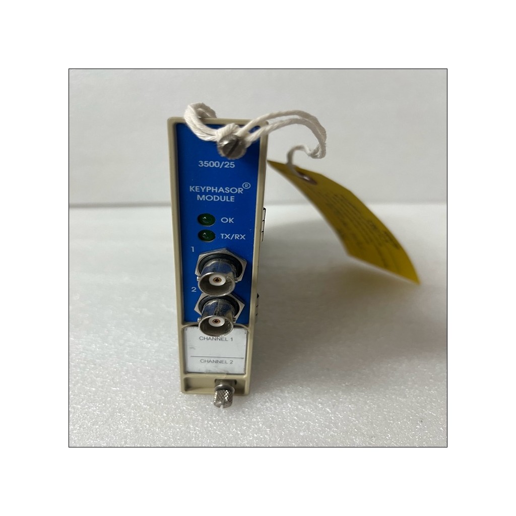
Bently Nevada Vibration Monitoring 3500
Bently Nevada 3500/72-01-00
3500 System Module
Bently Nevada 3500/72-01-00 3500 System Module. Input: Impedance 10 kΩ; Power: Consumption 7.7 watts, nominal.
- Available on request
Availability & pricing
Pricing is available on request — send an RFQ for a same-day quote.
Technical specifications
| Signal Accepts from 1 to 4 proximity | probe signals |
|---|---|
| Input | Impedance 10 kΩ |
| Rod Position | 0.79 mV/µm (20 mV/mil), 3.94 mV/µm (100 mV/mil), or 7.87 mV/µm (200 mV/mil) |
| Rod Position 2 | 3.94 mV/µm (100 mV/mil), or 7.87 mV/µm (200 mV/mil) Rod Drop 3.94 mV/µm (100 mV/mil), or 7.87 mV/µm (200 mV/mil) |
| Compressor | 3.94 mV/µm (100 mV/mil), or 7.87 mV/µm (200 mV/mil) |
| Power | Consumption 7.7 watts, nominal |
| Rod Position Monitor is | operating properly. |
| Rod Position Monitor is | communicating with other modules in the 3500 rack. |
| The front of each monitor | has one coaxial connector for each channel. |
| Output | Impedance 510 Ω |
| The 3500/72M Recip Rod Position Monitor | returns the following data values from measurements used to monitor the machine: |
| Single Channel | Position Magnitude, Position Angle, Crank Angle, Pk-Pk Amplitude, Gap, 1X Amplitude, Not 1X Amplitude, 2X Amplitude |
| Pair Channel | Position Magnitude, Position Angle, Crank Angle, Pk-Pk Amplitude, Gap, 1X Amplitude, Not 1X Amplitude, 2X Amplitude |
| Channel | Average Piston Position, Average Probe Gap, |
| Instantaneous Piston | Position, |
| Hyper Channel | Pk-Pk Displacement, Gap, 1X Amplitude, Not 1X Amplitude, 2X Amplitude |
| Average piston | position Fixed 1 Hz to 600 Hz |
| Amplitude | Within ±0.33% of full-scale typical ±1% maximum |
| Position | magnitude Within ±0.33% of full-scale typical ±1% maximum |
| Angle | (paired only) Within ±1° typical ±3° maximum |
| Angle | Within ±1° typical ±3° maximum |
| Gap | Within ±0.33% of full-scale typical ±1% maximum |
| Average piston | position Within ±0.33% of full-scale typical ±1% maximum |
| Instantaneous | piston position Within ±0.33% of full-scale typical ±1% maximum |
| Instantaneous | piston gap Within ±0.33% of full-scale typical ±1% maximum |
| Peak-Peak | filter Fixed 1 Hz to 600 Hz |
| Constant Q Notch filter | Minimum rejection in stopband of 34.9 dB over frequency range of 60 cpm to 15.8 times running speed 1X and 2X vector filter |
| Minimum rejection in | stopband of 57.7 dB 1X and 2X Vector and Not 1X parameters are valid for machine speeds of 60 cpm to 2130 cpm. |
| Position | magnitude (direct) Within ±0.33% of full-scale typical ±1% maximum |
| Gap | Within ±0.33% of full-scale typical ±1% maximum 1X Amplitude Within ±0.33% of full-scale typical ±1% maximum 2X Amplitude Within ±0.33% of full-scale typical ±1% maximum |
| Amplitude | Within ±3.0% of full scale typical |
| Average piston | position (direct) |
| Average piston | position (direct) Within ±0.33% of full-scale typical ±1% maximum |
| Average Gap | Within ±0.33% of full-scale typical ±1% maximum |
| Instantaneous | probe Gap Within ±0.33% of full-scale typical ±1% maximum |
| Constant Q Notch filter | Minimum rejection in stopband of 34.9 dB over frequency range of 60 cpm to 15.8 times running speed |
| Frequency Response | 1X Vector filter |
| Minimum rejection in stopband of 57.7 dB | 2X Vector filter |
| Minimum rejection in stopband of 57.7 dB | 1X and 2X Vector and Not 1X parameters are valid for machine speeds of 60 cpm to 2130 cpm. |
| Peak-Peak | magnitude Within ±0.33% of full-scale typical ±1% maximum |
| Amplitude | Within ±0.33% of full-scale typical |
| Dimensions | (Height x Width x Depth) 241.3 mm x 24.4 mm x 241.8 mm (9.50 in x 0.96 in x 9.52 in) |
| Dimensions | (Height x Width x Depth) 241.3 mm x 24.4 mm x 99.1 mm (9.50 in x 0.96 in x 3.90 in) |
| Dimensions | (Height x Width x Depth) 241.3 mm x 24.4 mm x 163.1 mm (9.50 in x 0.96 in x 6.42 in) |
| Proximitor / Seismic I/O | Module: -30°C to +65°C (-22°F to +149°F) |
| Termination) | 0°C to +65°C (32°F to +149°F) |
| Temperature | -40°C to +85°C (-40°F to +185°F) Humidity 95% |
| Software to set alert levels | for each value measured by the monitor and danger setpoints for any two of the values measured by the monitor. |
| Alarms are adjustable from | 0 to 100% of full-scale for each measured value. However, when the full-scale range exceeds the range of the transducer, the range of the transducer will limit the setpoint. |
| Accuracy of | alarm setpoints Within 0.13% of the desired value |
| Alert From one to 60 seconds in | one second intervals |
| Danger | 0.1 seconds (nominal) or from one to 60 seconds in one second intervals |
| OK Channel defeat is | disabled for all Rod Position and Rod Drop configurations. |
| As a hyper-compressor | monitor, when both transducers are NOT OK, the monitor issues a Danger alarm immediately. |
| Rod Position Monitor | 3500/72-01-00 A: I/O Module Type 01= I/O Module with Internal Terminations B: Hazardous Area Approval Option 00 =None |
Description
The Bently Nevada 3500/72-01-00 is a 3500 system module for the 3500 Machinery Protection System. It conditions field transducer signals into vibration and position measurements and compares them against programmable alarm setpoints inside the 3500 rack. Dimensions are (height x width x depth) 241.3 mm x 24.4 mm x 241.8 mm (9.50 in x 0.96 in x 9.52 in) It monitors critical rotating equipment such as turbines, compressors, and pumps, and communicates monitor status and measured values to the 3500 rack and to recorder outputs for machinery protection. Configuration is performed with 3500 Rack Configuration Software; no field calibration is required.
Ordering & Configuration
- Signal Accepts from 1 to 4 proximity: probe signals.
Electrical & Signal
- Alarms are adjustable from: 0 to 100% of full-scale for each measured value. However, when the full-scale range exceeds the range of the transducer, the range of the transducer will limit the setpoint..
- Accuracy of: alarm setpoints Within 0.13% of the desired value.
Environmental Ratings
- Temperature: -40°C to +85°C (-40°F to +185°F) Humidity 95%.
Physical & Mechanical
- Dimensions: (Height x Width x Depth) 241.3 mm x 24.4 mm x 241.8 mm (9.50 in x 0.96 in x 9.52 in).
- Dimensions: (Height x Width x Depth) 241.3 mm x 24.4 mm x 99.1 mm (9.50 in x 0.96 in x 3.90 in).
- Dimensions: (Height x Width x Depth) 241.3 mm x 24.4 mm x 163.1 mm (9.50 in x 0.96 in x 6.42 in).
Specifications
- Input: Impedance 10 kΩ.
- Rod Position: 0.79 mV/µm (20 mV/mil), 3.94 mV/µm (100 mV/mil), or 7.87 mV/µm (200 mV/mil).
- Rod Position 2: 3.94 mV/µm (100 mV/mil), or 7.87 mV/µm (200 mV/mil) Rod Drop 3.94 mV/µm (100 mV/mil), or 7.87 mV/µm (200 mV/mil).
- Compressor: 3.94 mV/µm (100 mV/mil), or 7.87 mV/µm (200 mV/mil).
- Power: Consumption 7.7 watts, nominal.
- Rod Position Monitor is: operating properly..
- Rod Position Monitor is: communicating with other modules in the 3500 rack..
- The front of each monitor: has one coaxial connector for each channel..
- Output: Impedance 510 Ω.
- The 3500/72M Recip Rod Position Monitor: returns the following data values from measurements used to monitor the machine:.
- Single Channel: Position Magnitude, Position Angle, Crank Angle, Pk-Pk Amplitude, Gap, 1X Amplitude, Not 1X Amplitude, 2X Amplitude.
- Pair Channel: Position Magnitude, Position Angle, Crank Angle, Pk-Pk Amplitude, Gap, 1X Amplitude, Not 1X Amplitude, 2X Amplitude.
- Channel: Average Piston Position, Average Probe Gap,.
- Instantaneous Piston: Position,.
- Hyper Channel: Pk-Pk Displacement, Gap, 1X Amplitude, Not 1X Amplitude, 2X Amplitude.
- Average piston: position Fixed 1 Hz to 600 Hz.
- Amplitude: Within ±0.33% of full-scale typical ±1% maximum.
- Position: magnitude Within ±0.33% of full-scale typical ±1% maximum.
- Angle: (paired only) Within ±1° typical ±3° maximum.
- Angle: Within ±1° typical ±3° maximum.
- Gap: Within ±0.33% of full-scale typical ±1% maximum.
- Average piston: position Within ±0.33% of full-scale typical ±1% maximum.
- Instantaneous: piston position Within ±0.33% of full-scale typical ±1% maximum.
- Instantaneous: piston gap Within ±0.33% of full-scale typical ±1% maximum.
- Peak-Peak: filter Fixed 1 Hz to 600 Hz.
- Constant Q Notch filter: Minimum rejection in stopband of 34.9 dB over frequency range of 60 cpm to 15.8 times running speed 1X and 2X vector filter.
- Minimum rejection in: stopband of 57.7 dB 1X and 2X Vector and Not 1X parameters are valid for machine speeds of 60 cpm to 2130 cpm..
- Position: magnitude (direct) Within ±0.33% of full-scale typical ±1% maximum.
- Gap: Within ±0.33% of full-scale typical ±1% maximum 1X Amplitude Within ±0.33% of full-scale typical ±1% maximum 2X Amplitude Within ±0.33% of full-scale typical ±1% maximum.
- Amplitude: Within ±3.0% of full scale typical.
- Average piston: position (direct).
- Average piston: position (direct) Within ±0.33% of full-scale typical ±1% maximum.
- Average Gap: Within ±0.33% of full-scale typical ±1% maximum.
- Instantaneous: probe Gap Within ±0.33% of full-scale typical ±1% maximum.
- Constant Q Notch filter: Minimum rejection in stopband of 34.9 dB over frequency range of 60 cpm to 15.8 times running speed.
- Frequency Response: 1X Vector filter.
- Minimum rejection in stopband of 57.7 dB: 2X Vector filter.
- Minimum rejection in stopband of 57.7 dB: 1X and 2X Vector and Not 1X parameters are valid for machine speeds of 60 cpm to 2130 cpm..
- Peak-Peak: magnitude Within ±0.33% of full-scale typical ±1% maximum.
- Amplitude: Within ±0.33% of full-scale typical.
- Proximitor / Seismic I/O: Module: -30°C to +65°C (-22°F to +149°F).
- Termination): 0°C to +65°C (32°F to +149°F).
- Software to set alert levels: for each value measured by the monitor and danger setpoints for any two of the values measured by the monitor..
- Alert From one to 60 seconds in: one second intervals.
- Danger: 0.1 seconds (nominal) or from one to 60 seconds in one second intervals.
- OK Channel defeat is: disabled for all Rod Position and Rod Drop configurations..
- As a hyper-compressor: monitor, when both transducers are NOT OK, the monitor issues a Danger alarm immediately..
- Rod Position Monitor: 3500/72-01-00 A: I/O Module Type 01= I/O Module with Internal Terminations B: Hazardous Area Approval Option 00 =None.
Model Comparison
Compare the 3500/72-01-00 against the closest Bently Nevada configurations below to confirm ordering options, ratings and physical interchange.
| Model | Dimensions | The front of each monitor | Output | Temperature | Signal Accepts from 1 to 4 proximity | Input | Power | Frequency Response |
|---|---|---|---|---|---|---|---|---|
| 3500/72-01-00 | (Height x Width x Depth) 241.3 mm x 24.4 mm x 163.1 mm (9.50 in x 0.96 in x 6.42 in) | has one coaxial connector for each channel. | Impedance 510 Ω | -40°C to +85°C (-40°F to +185°F) Humidity 95% | probe signals | Impedance 10 kΩ | Consumption 7.7 watts, nominal | 1X Vector filter |
| 3500/70-01-00 | (Height x Width x | has one coaxial connector for each channel. | Impedance 550 Ω typical Protection Each connector is shortcircuit protected. | -40°C to +85°C (-40°F to +185°F) Humidity 95% | probe signals. | impedance 10 kΩ acceleration input >1 MΩ velocity input | consumption 7.7 watts, nominal | — |
| 3500/77-03-00 | — | has one coaxial connector for each channel. Each connector is short-circuit protected. | Impedance 550 Ω | -40°C to +85°C (-40°F to +185°F) Humidity 95%, non-condensing | — | — | — | — |
| 3500/77M 176449-07 | — | — | — | — | — | — | — | 0 to 5.5 kHz on all configured pressure channels |
| 3500/33-01-00 | — | — | — | — | — | — | — | — |
| 3500/42-01-02 | (Height x Widthx Depth) 241.3 mm x 24.4 mm x 163.1mm (9.50 in x 0.96 in x 6.42 in) | — | — | — | — | — | — | — |
| 3500/42-02-00 | (Height x Widthx Depth) 241.3 mm x 24.4 mm x 241.8mm (9.50 in x 0.96 in x 9.52 in) | — | — | — | — | — | — | — |
Frequently asked questions
What is the Bently Nevada 3500/72-01-00 and what does it do?
The Bently Nevada 3500/72-01-00 is a component for the 3500 Machinery Protection System. It conditions field transducer signals into vibration and position measurements and compares them against user-programmable alarm setpoints within the 3500 rack.
What are the physical dimensions of the 3500/72-01-00?
The 3500/72-01-00 measures (Height x Width x Depth) 241.3 mm x 24.4 mm x 241.8 mm (9.50 in x 0.96 in x 9.52 in) and weighs It occupies a standard 3500 rack slot and installs on the rack backplane.
How is the 3500/72-01-00 installed and configured?
The 3500/72-01-00 mounts in a 3500 rack rear slot and draws power from the rack backplane. Channels are configured with 3500 Rack Configuration Software; alarm setpoints and full-scale ranges are set in software with no field calibration required.
Related & compatible parts

Bently Nevada · 3500
3500/94M 119M6509-03
Bently Nevada 3500/94M 119M6509-03 3500 System Module. Power: consumption 4.6 watts max; RS232 port: (I/0) Touch controller data.
Bently Nevada
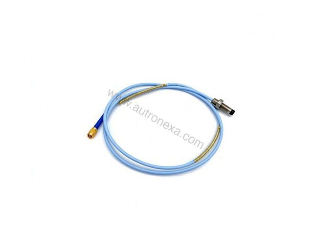
106769-01
Genuine Bently Nevada 106769-01 interconnect cable, 1 ft (0.3 m), 0.5 kg. Verified surplus stock for reliable transducer-to-monitor…
Bently Nevada · 31000 / 32000 Series
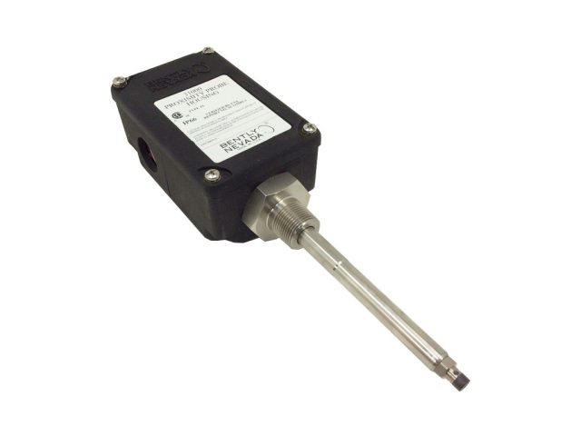
31000-00-00-00-082-03-02
Bently Nevada 31000-00-00-00-082-03-02 Proximity Probe Housing. Probe Cable Length: Probe cable not required; O-Ring Material: Neoprene®.
Bently Nevada
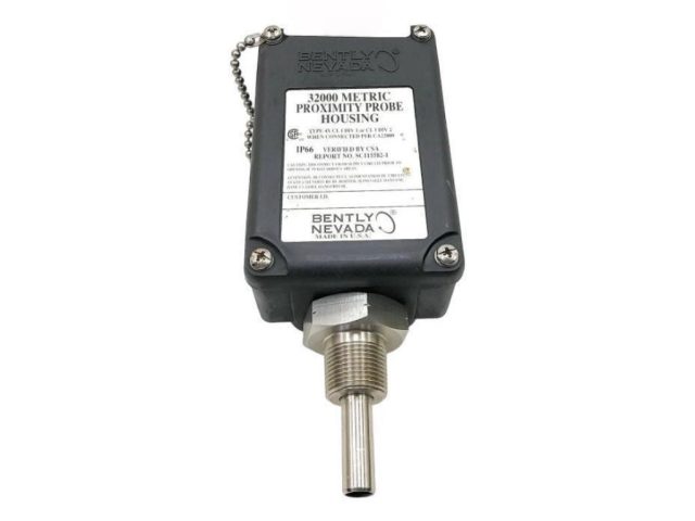
32000-16-05-08-070-03-02
Bently Nevada 32000-16-05-08-070-03-02 Proximity Probe Housing. Probe Penetration: 70 mm; Standoff Adapter: 80 mm.
News & guides for Bently Nevada
Bently Nevada AnomAlert: Motor Anomaly Detection Without Sensors
TL;DR: The Bently Nevada AnomAlert is a motor anomaly detector that watches a three-phase motor through its voltage and current…

Bently Nevada 3500/06 Weatherproof Housing: Ratings, Purging and Mounting Limits
TL;DR: The weatherproof enclosure for a Bently Nevada 3500 rack is the 3500/06, not the 3500/01 — 3500/01 is the…
Bently Nevada 3500/91 EGD Gateway: Mark VIe Interface, Slots and Limits
TL;DR: The Bently Nevada 3500/91 is the EGD (Ethernet Global Data) communication gateway for a 3500 rack. It publishes rack,…

Bently Nevada 3500/50M Tachometer Module: Channels, Alarms, Spares
The 3500/50M is a two-channel speed module with no onboard relay contacts and no numeric display. What it measures, how…
Bently Nevada Orbit 60 conneX: Bidirectional DCS Interface
Bently Nevada’s Orbit 60 condition monitoring platform connects to the rest of the plant through conneX—a bidirectional digital interface that…
Bently Nevada 3500 Machinery Protection System: Specifications and Configuration
The Bently Nevada 3500 Machinery Protection System is a rack-based, modular monitoring and protection platform for rotating machines such as…
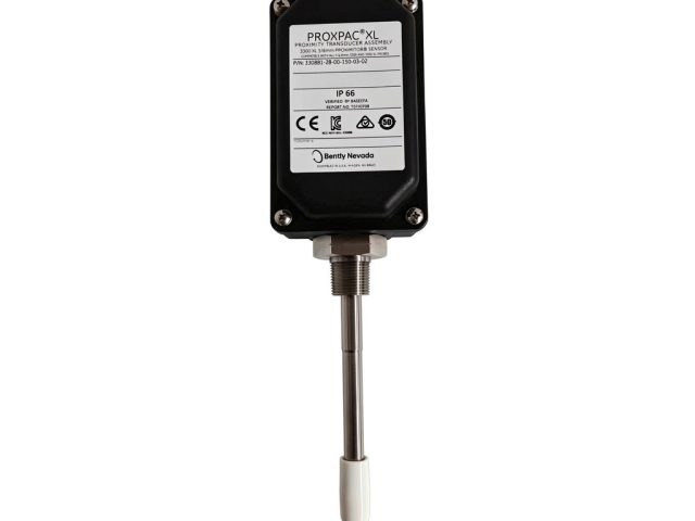
Bently Nevada 3300 XL Proximity Probe: Materials, Ratings, and Mounting
The Bently Nevada 3300 XL proximity transducer system measures radial vibration, axial position, and phase reference on rotating machinery shafts.…
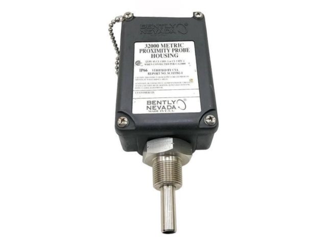
Bently Nevada 32000 Metric Probe Housing: Construction and Protection Ratings
The Bently Nevada 32000 Metric Proximity Probe Housing is a mounting assembly that secures a 3300 XL proximity probe in…